- 您现在的位置:买卖IC网 > Sheet目录367 > UEVM4430G-01-00-00 (Circuitco Electronics LLC)PANDABOARD
Revision 0.6
OMAP TM 4 PandaBoard System
Reference Manual
November 29, 2010
DOC-21010
GPIO
GPIO_41
GPIO_60
Dir
O
O
Signal Name
HDMI_LS_OE
HDMI_CT_CP_HPD
Description
TPD12S015 Level Shifter and internal LDO Enable
1 = Enabled, 0 = Disabled
TPD12S015 DC/DC Converter and Hot-Plug Detect
Enable 1 = Enabled, 0 = Disabled
Table 4: HDMI GPIO Definitions
2.12
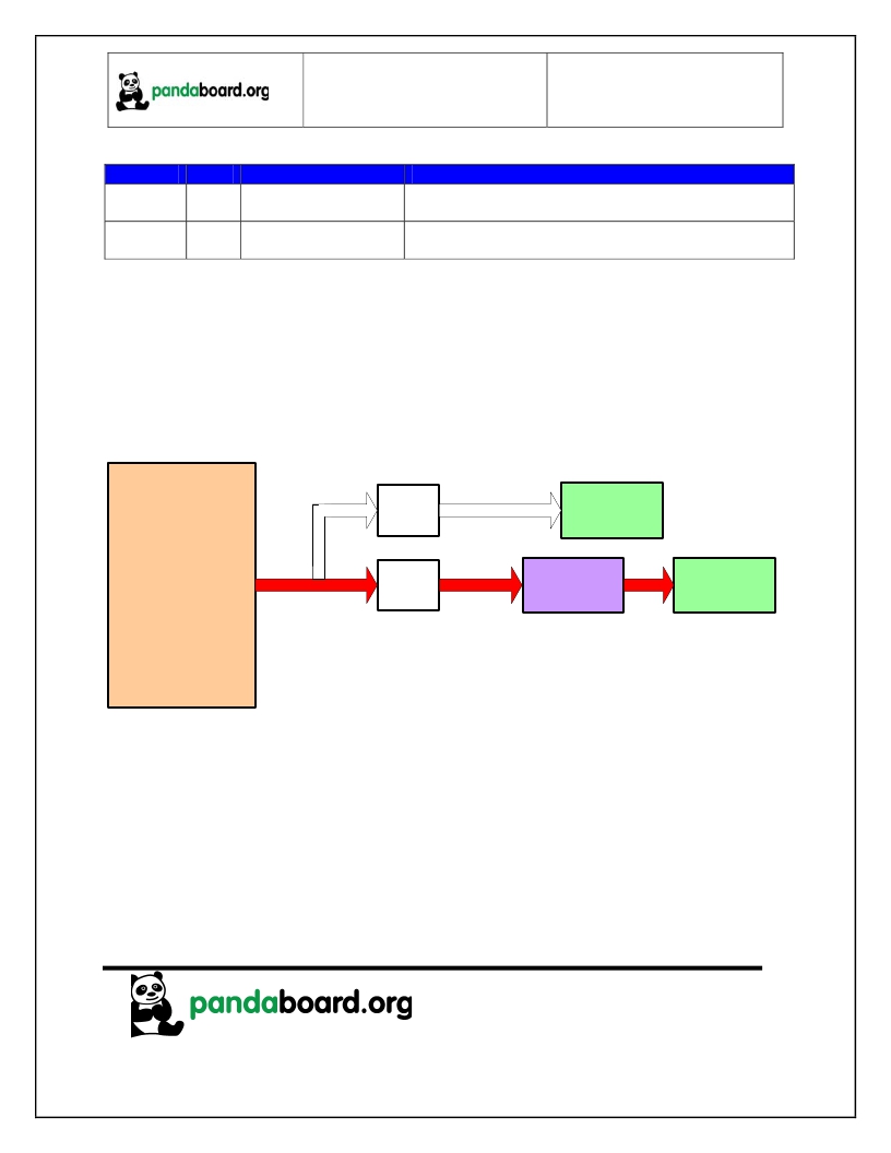
Display Interface
The PandaBoard provides two possible options for the usage of the OMAP4430 parallel display signals.
The first option (the as-shipped default configuration) routes them to a TFP410 DVI transmitter, whose
output feeds an onboard DVI-D connector. The second option routes them to a pair of 20-pin LCD
expansion connectors (J1 and J4). Both of these possible options are discussed in the following
paragraphs. See Figure 8 for a diagram of the PandaBoard Display Interface. The path shown in red in
OMAP4430
Processor
DISPC2_DATA(23:0)
R-Mux
(DNI)
LCD Expansion
Connectors
(J1 & J4)
DISPC2_PCLK
DISPC2_VSYNC
DISPC2_HSYNC
DISPC2_DE
R-Mux
(Default)
TFP410PAP
DVI Transmitter
(U2)
DVI-D
Connector
(P1)
Figure 8 – Panda Display Interface Block Diagram
2.12.1 Parallel Display DVI-D connector
As mentioned previously, the as-shipped parallel display interface configuration for the PandaBoard is
with the parallel display interface signals from OMAP driven to a TFP410 DVI transmitter, whose output
feeds an onboard DVI-D connector. See Figure 9 for a block diagram of this interface.
Page 30 of 82
发布紧急采购,3分钟左右您将得到回复。
相关PDF资料
UEVM4460G-02-01-00
PANDABOARD ES
UHDM7218BPA
PLATE BARRIER 71.86X17.87" GRY
UHDM7218ECA
PLATE END 71.86X17.87" GREY
UHDM7218EPA
PLATE END 71.86X17.87" GREY
UHDM8418BPA
PLATE BARRIER 83.9X17.9X0.1" GRY
UHDM8418ECA
PLATE END 83.9X17.9X2.5" GREY
UHDM8418EPA
PLATE END 83.87X17.87" GREY
UHDM8424BPA
PLATE BARRIER 83.9X23.9X0.1" GRY
相关代理商/技术参数
UEVM4430G-03-00-00
制造商:PandaBoard 功能描述:Development Boards & Kits - ARM PANDABOARD
UEVM4460G-02-01-00
功能描述:开发板和工具包 - ARM PANDABOARD ES
RoHS:否 制造商:Arduino 产品:Development Boards 工具用于评估:ATSAM3X8EA-AU 核心:ARM Cortex M3 接口类型:DAC, ICSP, JTAG, UART, USB 工作电源电压:3.3 V
UEVM4460G-02-02-00
制造商:SVTRONICS INC 功能描述:PANDABOARD ES
UEVM5432-G-01-00-00
制造商:SVTRONICS INC 功能描述:EVAL BOARD FOR OMAP 5
UEVM5432G-02-12-00
功能描述:OMAP5432 OMAP? MPU ARM? Cortex?-A15, Cortex?-M4 Embedded Evaluation Board 制造商:svtronics inc. 系列:OMAP? 零件状态:有效 板类型:单板计算机 类型:MPU 核心处理器:ARM? Cortex?-A15,Cortex?-M4 操作系统:Android,Linux 平台:- 配套使用产品/相关产品:OMAP5432 安装类型:固定 内容:板 标准包装:1
UEX220-3U
功能描述:印刷电路板和试验板 EXTENDER 3U UNCOMMIT 3.937X11.75X.062"
RoHS:否 制造商:3M Electronic Solutions Division 产品:Jumper & Insulated Wires 描述/功能:Jumper wire, 22 AWG 0.1 inch 长度:0.1 in 宽度:
UEX220-6U
功能描述:EXTENDR UNCOMM 160-PINS 6UX12.2" RoHS:是 类别:盒,外壳,支架 >> 卡架 - 配件 系列:Vectorbord® 标准包装:1 系列:VectorPak™ 附件类型:EFP 模块 适用于相关产品:PCB
UEZ334K100
制造商:THO 功能描述:RMX433X100 THOMSON IN 2103-C
